Active Harmonic Filter (AHF)
Definition of harmonics and its ill Effects
A load which draws a non-sinusoidal (distorted) current, when a pure sinusoidal voltage is applied, is a non-linear load.Deviation from the ideal sinusoidal waveform is called harmonic distortion.The flow of distorted current through the system impedance causes to increase voltage distortion in the network resulting deterioration of the supply voltage quality. All electrical devices are designed to operate with pure sinusoidal waves. A distorted sine wave may lead to such adverse effect are more pervasive for consumers and often seen in the following form.
-
Overheating of transformers, motors and cables
-
Overloading of neutral conductors
-
Malfunction/premature failure of equipment
-
Capacitor overloading and network resonance
-
Undue tripping of circuit breakers and blowing of fuses
-
Disturbances to sensitive loads, control and monitoring devices, computer and networking equipment’s.
-
Causes increase in replacement cost due to reduced life of equipment’s, increase in capital cost of installation due to over sizing of equipment’s and increase in operating cost due to overloading of equipment’s.
-
DG heating and hunting
Type of Loads which are sources of harmonics:
Variable speed Drives, Induction furnaces, Static converters, UPS systems, DC Power Supplies, welding machines, Induction furnaces, Solid state elevator controls, office equipment’s like computers, servers, printers, photocopy machines, Household appliances such as fluorescent lightings, TV, light dimmers, microwave ovens, saturated magnetic devices.
The conventional solution to address this issue is to connect Passive filter i.e series combination of reactor and capacitor but this have certain limitations like Filtering efficiency depends on network parameters, danger for overloading filter components, difficult to extend, possibility of resonance, multiple branches required for filtering more than one harmonic and hence large space requirement.
To cater this problem, Unistar has developed very efficient, reliable and flexible equipment called Smart Power Conditioner i.e Active Harmonic Filter (AHF)
Working Principle
Unistar Power Quality Improvement device which is solid state IGBT based power converter which monitors harmonic currents generated by nonlinear load. It generates opposite phase shifted harmonic currents of the same amplitude and inject to the network to cancel the load harmonic current and then to obtain the sinusoidal current (refer in Fig.1 below) and hence voltage in the utility and also improving power quality and compensating unbalance currents.
When the harmonic mitigation is needed, the advance control algorithm programmed in Digital signal processor (DSP) calculates the harmonic spectrum through fast Fourier transform (FFT) technique from load current measured to find out harmonic currents of order 2nd to 50th. Due to the advanced microprocessor and fast switching of the IGBT inverter topology, ultra-fast reaction time of < 200 micro seconds is possible.
Advanced control algorithm ensures step less correction and instantaneous compensation.
Active Harmonic Filter is connected in shunt with nonlinear load and current feedback is taken to the AHF controller from the Current Transformer connected at Line side or Transformer secondary.
The distorted non-linear sinusoidal waveform at load side will be cleaned and pure sine wave is available at line or supply side as in Fig.2 above.
-
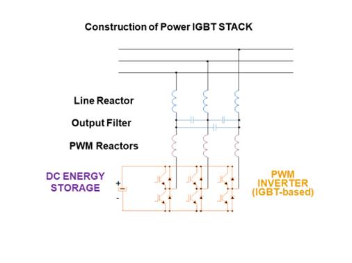
The major Power Circuit in Active Harmonic Filter includes IGBT Power Stack having various power components like 6 no. IGBTs (Inverted Gate Bipolar Transistor) i.e 2 in series for each phase of suitable current and voltage rating connected to common DC bus with Capacitor called energy storage capacitor mounted on Aluminum heatsink to dissipate the heat generated due to IGBT switching losses. Sandwich type DC bus is formed to connect IGBT stack and DC capacitor to reduce the inductance of the stack.
-
Another important part of power stack is coupling inductor or PWM reactor which couples the line side and Inverter side. Voltage across the inductor decides the weather reactive power will be supplied from the inverter to mains or reactive power will be absorbed from mains to Inverter depend on DC capacitor Voltage which is controlled by DSP Processor.
-
Line side filter is used to filter out high frequency unwanted signals and not to flow towards mains supply. This is generally Ԓ type filter formed by AC filter capacitor and choke.
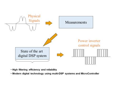
Above image shows the measurement of polluted or distorted signals is done by advanced DSP processor which generates the control signals to operated IGBT Inverter switching at high frequency i.e. 12 kHz to 20 kHz.
AHF OPERATION
AHF produces three-phase AC Voltage from a DC Bus using Pulse Width Modulation (PWM) technique. The Inverter generated voltage is coupled to the source voltage (Grid/Generator) through a coupling reactor as mentioned above. By varying the magnitude of AC terminal voltage of the Inverter, power exchange takes place between filter and the AC Source (Grid/Generator). If the magnitude of Inverter output voltage is more than the AC Source Voltage, current flows from the filter to the Supply. If the magnitude of Inverter output voltage is less than the AC Source Voltage, current flows from supply voltage into the filter. If amplitude of Inverter output voltage is equal to the AC Source voltage, no current flow takes place between Supply and Inverter and the filter is said to be in a floating state of operation. Thus, just by manipulating the voltage at the output terminal of the Power Inverter Stack, the device can be programmed to generate current waveform of any shape, size or phase i.e it can supply or absorb reactive power, harmonic current or can balance load current. It cannot generate/provide Active Power to the load.
With the advancements in semi-conductor technology and new developments in the field of Power Electronics. Various topologies have come up. Each with its own advantages and dis-advantages. Above explained in two Level topology, whereas now three level and multilevel topologies have come up having its own advantages and disadvantages as below with understanding.
2-Level Topology
-
Output Voltage varies between +Ud/2 and -Ud/2
-
2 IGBTs/phase
-
Common DC Bus for all 3 phases
-
High DC Voltage e.g: 750V for 415V model
Advantages
-
Simple topology. Fewer components/electronics
-
Simplest control scheme
-
Easy availability of components/spares
-
Rugged construction
-
Stack failure will require replacement of 6 IGBTs + drivers (3 phase)
Dis-Advantages
-
Slightly higher losses ~20W/A
-
Higher value of magnetics required
-
Not recommended above 3Ph-415V application
3- Level Topology
It is the extension of 2-Level topology having few advantages over it.
Topology
Output Voltage varies between +Ud/2, 0 and -Ud/2
Advantages
-
Simpler construction. Easy availability of components
-
4 IGBTs/phase
-
Lowest losses 12~15W/A
-
Lowest magnetics value
-
DC voltage variable by adaptive artificial neural network logic.
-
Modular construction
-
1% less losses than 2-level AHF
Major Features of Unistar-Active harmonic Filter called as Unistar Power Quality Improvement device below..
-
Unistar AHF is IGBT based advanced Active Harmonic filter available from 30 to300A rating in standalone panel type design.
-
Harmonic correction from 2nd order to 50th Order(2-level)/ 2nd order to 71st order(3level)
-
PF compensation up to Unity from 0.6 lag to 0.9 lead
-
rating can be extended with paralleling of units
-
7" Touch Screen TFT Display
-
Closed loop, 32bit FPU DSP based fully digital control. Internal CAN BUS communication for increased reliability
-
Standard model is up to 440V in 2-Level design and higher voltages up to 690 V can be supplied with 3 Level design along with step down transformer at 440V side.
-
Standard models available with for IP 20.
-
PF Compensation, Harmonic filtering are available by default.
-
Load Balancing feature is optional (Negative Sequence Current Component Elimination)
-
Filters all selectable harmonics simultaneously in a range up to the 50th harmonic
-
Operates with closed loop control for best accuracy
-
Response Time <10 mSec (upto 80% filtering)
-
Filter Power Loss: Up to 2.5 % of equipment rating for standard design
-
Installation: Free standing, Floor Mounting with Front access
-
Reference Standard: IEEE519 for compensated Harmonics
-
Protection: MCCB.
-
Neutral Compensation available (Zero Sequence Current Component Elimination)
-
Ultra-fast reaction time < 200 μS
Major Advantages:
-
Step-less compensation
-
No risk of resonance
-
No voltage transients
-
Fully compatible with future load expansion
-
Reduced energy bills by elimination of losses and improvement of true PF
-
Reduced failures by elimination of distortions